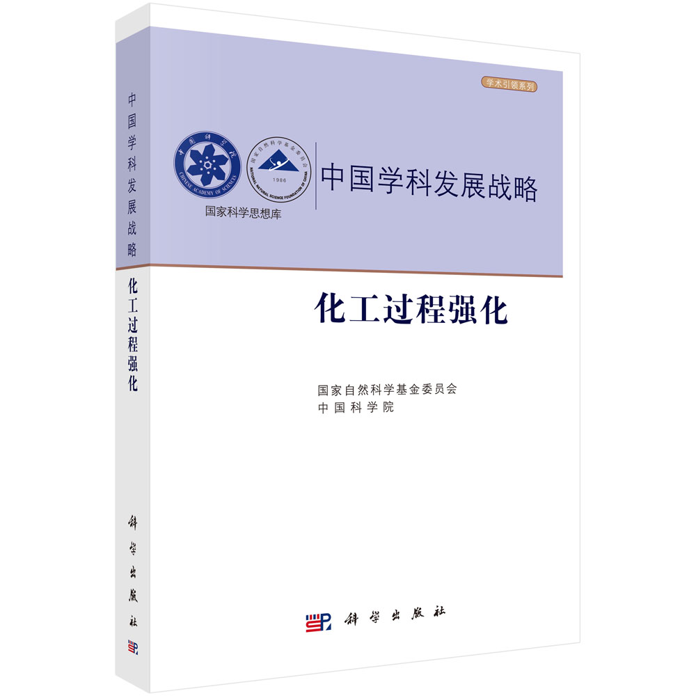
本书系统讨论用于电子、光电子和MEMS器件的2.5D、3D,以及3D IC集成和封装技术的最新进展和未来可能的演变趋势,同时详尽讨论IC三维集成和封装关键技术中存在的主要工艺问题和可能的解决方案。通过介绍半导体工业中的集成电路发展,以及摩尔定律的起源和演变历史,阐述三维集成和封装的优势和挑战,结合当前三维集成关键技术的发展重点讨论TSV制程与模型、晶圆减薄与薄晶圆在封装组装过程中的拿持晶圆键合技术、三维堆叠的微凸点制作与组装技术、3D硅集成、2.5D/3D IC和无源转接板的3D IC集成、三维器件集成的热管理技术、封装基板技术,以及存储器、LED、MEMS、CIS 3D IC集成等关键技术问题,最后讨论PoP、Fanin WLP、eWLP、ePLP等技术。
样章试读
目录
- 目录
前言
致谢
导读
第1章 半导体集成电路封装3D集成 1
1.1 引言 1
1.2 3D集成 1
1.3 3D IC封装 4
1.4 3D Si集成 5
1.5 3D IC集成 7
1.5.1 混合存储器立方(HMC) 7
1.5.2 Wide I/O动态随机存储器和Wide I/O 28
1.5.3 高带宽存储器(HBM)10
1.5.4 Wide I/O存储器 (Logic-on-Logic) 10
1.5.5 无源转接板 (2.5D IC集成) 10
1.6 TSV技术时代供应链 13
1.6.1 前道工艺 (Front-End-of-Line) 13
1.6.2 后道工艺 (Back-End-of-Line ) 13
1.6.3 封装与测试(Outsourced Semiconductor Assembly and Test) 13
1.7 TSV技术时代供应链——谁制造TSV? 13
1.7.1 Via-First TSV工艺 13
1.7.2 Via-Middle TSV工艺 13
1.7.3 Via-Last TSV工艺(from the front Side) 13
1.7.4 Via-Last TSV工艺(from the Back Side) 13
1.7.5 无源TSV转接板? 14
1.7.6 谁想用无源转接板TSV技术? 14
1.7.7 总结和建议 14
1.8 TSV技术时代供应链—谁负责中道工艺MEOL,装配和测试? 14
1.8.1 Wide I/O存储器(面对背)的Via-Middle TSV制造工艺 14
1.8.2 Wide I/O存储器(面对面)的Via-Middle TSV制造工艺 16
1.8.3 Wide I/O DRAM的Via-Middle TSV制造工艺 16
1.8.4 基于带有TSV/RDL转接板的2.5D IC集成 17
1.8.5 总结与建议 18
1.9 CMOS图像传感器与TSVs 19
1.9.1 东芝Dynastron图像传感器 19
1.9.2 意法半导体的VGA CIS摄像头模块 19
1.9.3 三星S5K4E5YX BSI CIS图像传感器 20
1.9.4 东芝HEW4 BSI TCM5103PL图像传感器 20
1.9.5 Nemotek CIS图像传感器 21
1.9.6 索尼ISX014堆叠相机传感器 22
1.10 使用TSV技术的微机电系统 22
1.10.1 意法半导体的MEMS惯性传感器 22
1.10.2 Discera的MEME振荡器 22
1.10.3 Avago的FBAR MEMS滤波器 24
1.11 参考文献 24
第2章 硅通孔的建模和测试 29
2.1 引言 29
2.2 TSV的电气模型 29
2.2.1 通用TSV结构的解析模型和方程 29
2.2.2 TSV模型的频域验证 32
2.2.3 TSV模型的时域验证 35
2.2.4 TSV的电气设计指南 38
2.2.5 总结与建议 38
2.3 TSV的热模拟 40
2.3.1 铜填充TSV等效热电导率法 40
2.3.2 单个TSV的热特性 43
2.3.3 铜填充TSV的等效热导率方程 47
2.3.4 等效TSV热电导率方程验证 48
2.3.5 总结与建议 51
2.4 TSV机械建模和测试技术 53
2.4.1 铜填充TSV和周围硅的透射电镜 53
2.4.2 TSV制造的Pumping实验结果 55
2.4.3 热冲击下铜Pumping 58
2.4.4 铜填充TSV的Keep-Out-Zone区 61
2.4.5 总结与建议 64
2.5 参考文献 64
第3章 应力传感器用于薄晶圆拿持和应力测量 67
3.1 引言 67
3.2 压阻式压力传感器的设计与制作 67
3.2.1 压阻式压力传感器的设计 68
3.2.2 压力传感器的制作 69
3.2.3 总结与建议 71
3.3 应力传感器在薄晶圆拿持中的应用 73
3.3.1 压阻式压力传感器的设计、制造及校准 73
3.3.2 晶圆减薄后的应力测量 77
3.3.3 总结与建议 78
3.4 应力传感器在晶圆凸块制造中的应用 79
3.4.1 UBM制作的应力 79
3.4.2 干膜处理后的应力 79
3.4.3 焊料凸点工艺后的应力 83
3.4.4 总结与建议 84
3.5 应力传感器在嵌入式超薄芯片的跌落试验中的应用 84
3.5.1 Test Vehicle与制造 84
3.5.2 实验装置及流程 85
3.5.3 原位应力测量结果 86
3.5.4 可靠性测试 88
3.5.5 总结与建议 88
3.6 参考文献 90
第4章 封装基板技术 93
4.1 引言 93
4.2 三维集成电路倒装芯片积层法封装基板 93
4.2.1 表面层压电路技术 93
4.2.2 积层法封装基板发展趋势 95
4.2.3 总结与建议 96
4.3 无芯封装基板 96
4.3.1 无芯封装基板的优缺点 96
4.3.2 采用无芯基板的替代硅转接板 97
4.3.3 无芯基板翘曲问题和解决方案 99
4.3.4 总结与建议 102
4.4 积层法封装基板的最新进展 102
4.4.1 薄膜层上建立封装基板层 102
4.4.2 翘曲和可靠性结果 106
4.4.3 总结与建议 107
4.5 参考文献 107
第5章 微凸点制造、装配和可靠性 109
5.1 引言 109
5.2 制造、装配和25μm间距凸点的可靠性 109
5.2.1 Test Vehicle 109
5.2.2 微凸点结构 110
5.2.3 ENIG焊盘的结构 112
5.2.4 25μm-pitch间距微凸点制造 113
5.2.5 硅基板上ENIG焊盘的制作 114
5.2.6 热压键合组装 116
5.2.7 底部填充的评估 120
5.2.8 可靠性评估 121
5.2.9 总结与建议 122
5.3 制造、装配和20μm间距微凸点可靠性 123
5.3.1 Test Vehicle 123
5.3.2 Test Vehicle的装配 124
5.3.3 热压键合微连接的形成 124
5.3.4 缝隙填充 125
5.3.5 可靠性试验 126
5.3.6 可靠性试验结果与讨论 127
5.3.7 微连接失效机理 130
5.3.8 总结与建议 133
5.4 制造、装配,以及15μm间距凸点的可靠性 134
5.4.1 微凸块和试验车辆的UBM垫 134
5.4.2 组装 135
5.4.3 CuSn凸点与ENIG焊盘组装 136
5.4.4 CuSn凸点和CuSn凸点组装 136
5.4.5 底部填充评估 137
5.4.6 总结与建议 138
5.5 参考文献 138
第6章 三维硅集成 143
6.1 引言 143
6.2 电子工业 143
6.3 摩尔定律和和超过摩尔定律 144
6.4 三维集成的原点 145
6.5 三维集成的概况与展望 146
6.5.1 硅三维集成键合方法 147
6.5.2 铜-铜(晶圆-晶圆)键合 148
6.5.3 铜-铜(晶圆-晶圆)后退火键合 150
6.5.4 铜-铜(晶圆-晶圆)常温键合 151
6.5.5 二氧化硅-二氧化硅(晶圆-晶圆)键合 151
6.5.6 晶圆-晶圆键合的几个注释154
6.6 3D硅集成技术挑战 154
6.7 三维硅集成EDA工具挑战 155
6.8 总结和建议 155
6.9 参考文献 157
第7 章2.5D/3D IC集成 161
7.1 引言 161
7.2 3D IC集成TSV工艺 162
7.2.1 片上微孔 162
7.2.2 Via-First工艺 163
7.2.3 Via-Middle工艺 163
7.2.4 前道Via-Last工艺 163
7.2.5 后道Via-Last工艺 163
7.2.6 总结与建议 165
7.3 3D IC的潜在应用 165
7.4 存储器芯片堆叠 165
7.4.1 芯片介绍 165
7.4.2 潜在产品 166
7.4.3 组装工艺 168
7.5 Wide I/O存储器或逻辑-逻辑堆叠 168
7.5.1 芯片 168
7.5.2 潜在产品 168
7.5.3 组装工艺 171
7.6 Wide I/O DRAM或混合内存立方 173
7.6.1 芯片 173
7.6.2 潜在产品 175
7.6.3 组装工艺 176
7.7 Wide I/O2和高带宽存储器 177
7.8 Wide I/O接口(2.5D IC集成)178
7.8.1 TSV/RDL转接板实际应用 178
7.8.2 转接板制造 180
7.8.3 TSV制造 181
7.8.4 RDL制造 183
7.8.5 RDL制造-聚合物/镀铜方法 183
7.8.6 RDL制造-大马士革方法 185
7.8.7 大马士革方法接触对准注释 188
7.8.8 后道工艺和组装 188
7.8.9 总结与建议 191
7.9 薄晶圆拿持 191
7.9.1 常规薄晶圆拿持方法 192
7.9.2 TI的TSV-WCSP集成工艺 192
7.9.3 TSMC的薄晶圆拿持 194
7.9.4 TSMC的无键合/拆键合工艺以及薄晶圆拿持 194
7.9.5 带有均温板的薄晶圆拿持 194
7.9.6 总结与建议 197
7.10 参考文献 199
第8章 基于转接板的3D IC集成 203
8.1 引言 203
8.2 基于TSV/RDL转接板的3D IC集成 203
8.3 双面贴装TSV/RDL转接板 203
8.3.1 结构 203
8.3.2 热分析-边界条件 206
8.3.3 热分析-TSV等效模型 206
8.3.4 热分析-焊料凸点/填充等效模型 206
8.3.5 热分析-结果 207
8.3.6 热机械分析-边界条件 209
8.3.7 热机械分析-材料性能 210
8.3.8 热机械分析-结果 211
8.3.9 TSV制造 214
8.3.10 顶部带有RDL的转接板制造 216
8.3.11 顶部带有RDL铜填充转接板的TSV露铜 217
8.3.12 底部带有RDL转接板制造 219
8.3.13 转接板电学特性 219
8.3.14 组装 221
8.3.15 总结与建议 224
8.4 在转接板两面组装芯片的TSV转接板 225
8.4.1 结构 225
8.4.2 热分析-材料性能 226
8.4.3 热分析-边界条件 226
8.4.4 热分析-结果和讨论 227
8.4.5 热机械分析-材料性能 230
8.4.6 热机械分析-边界条件 230
8.4.7 热机械分析-结果及讨论 230
8.4.8 转接板制造 233
8.4.9 晶圆微凸块 235
8.4.10 组装 237
8.4.11 总结与建议 241
8.5 成本低TSH转接板3D IC集成 243
8.5.1 新设计 243
8.5.2 电模拟 244
8.5.3 试验 246
8.5.4 顶部UBM/焊盘和铜凸块 247
8.5.5 底部UBM/焊盘和焊料 249
8.5.6 TSH转接板制作 249
8.5.7 组装 250
8.5.8 可靠性评估 253
8.5.9 总结与建议 257
8.6 参考文献 258
第9章 2.5D/3D IC集成的热管理 261
9.1 引言 261
9.2 设计理念 261
9.3 新设计 262
9.4 热分析等效模型 263
9.5 顶部芯片/散热器以及底部芯片的转接板 264
9.5.1 结构 264
9.5.2 材料性能 264
9.5.3 边界条件 264
9.5.4 仿真结果 266
9.6 顶部芯片/散热器以及底部芯片/热沉的转接板 267
9.6.1 结构和边界条件 267
9.6.2 仿真结果 268
9.7 顶部有四芯片与散热器的转接板 269
9.7.1 结构 269
9.7.2 边界条件 269
9.7.3 仿真结果 270
9.7.4 总结与建议 271
9.8 介于2.5D和3D IC集成之间的结构热性能 273
9.8.1 结构 273
9.8.2 有限元模 274
9.8.3 材料特性和边界条件 274
9.8.4 仿真结果-低功率应用 276
9.8.5 仿真结果-高功率应 用276
9.8.6 总结与建议 278
9.9 嵌入微流道的TSV转接板热管理系统 278
9.9.1 结构 278
9.9.2 适配器 278
9.9.3 热交换器 280
9.9.4 载板 280
9.9.5 系统集成 282
9.9.6 压降的理论分析 283
9.9.7 实验流程 284
9.9.8 结果及讨论 285
9.9.9 总结与建议 288
9.10 参考文献 289
第10章 嵌入式三维混合集成 291
10.1 引言 291
10.2 光电产品的趋势 291
10.3 基于PCB光波导的高速数据互连 293
10.3.1 聚合物光波导 293
10.3.2 模拟-光学耦合模型 295
10.3.3 模拟-系统链路设计 301
10.3.4 光电印制电路板的装配 302
10.3.5 光电印制电路板的测量结果 303
10.3.6 总结与建议 305
10.4 嵌入式板级光互连 305
10.4.1 聚合物光波导制作 305
10.4.2 45°微镜的制作 306
10.4.3 光电印制电路板的组装工艺 312
10.4.4 垂直光通道制作工艺 314
10.4.5 组装 314
10.4.6 总结与建议 315
10.5 新设计 317
10.6 嵌入式3D混合集成设计实例 318
10.6.1 光学设计、分析及结果 318
10.6.2 热设计、分析及结果 320
10.6.3 机械设计、分析及结果 322
10.6.4 总结与建议 324
10.7 带有应力消除缝隙的半嵌入式TSV转接板 326
10.7.1 设计理念 326
10.7.2 问题定义 327
10.7.3 半嵌入式TSV转接板的操作条件 327
10.7.4 半嵌入式TSV转接板的环境条件 332
10.7.5 总结与建议 333
10.8 参考文献 335
第11章 LED和集成电路三维集成 339
11.1 引言 339
11.2 现状及Haitz定律展望 339
11.3 LED已经走了很长的路!342
11.4 LED产品的四个关键部分 344
11.4.1 LED衬底外延沉积 344
11.4.2 LED器件的制备 345
11.4.3 LED封装和测试 345
11.4.4 LED组装 345
11.4.5 LED产品展望 346
11.5 LED和集成电路三维集成 348
11.5.1 惠普FCLED和薄膜FCLED 348
11.5.2 LED和IC的3D集成封装 349
11.5.3 LED和IC三维集成制造流程 351
11.5.4 总结与建议 356
11.6 2.5D IC和LED的集成 357
11.6.1 基于带有腔体以及铜填充TSV的硅载板的LED封装 358
11.6.2 基于腔体和TSV硅衬底的LED封装 361
11.6.3 LED晶圆级封装 365
11.6.4 总结和建议 369
11.7 LED和IC三维集成的热管理 369
11.7.1 新设计 372
11.7.2 3D IC和LED的集成:一个设计实例 372
11.7.3 边界值问题 372
11.7.4 仿真结果(通道高度700μm) 373
11.7.5 仿真结果(通道高度350μm) 377
11.7.6 总结与建议 377
11.8 参考文献 379
第12章 MEMS与集成电路的三维集成 383
12.1 引言 383
12.2 MEMS的封装 383
12.3 MEMS与集成电路三维设计 385
12.3.1 带有横向电馈通的MEMS和IC的三维集成 385
12.3.2 ASIC带有垂直电馈通的MEMS和IC的三维集成 386
12.3.3 封装盖帽带有垂直电馈通的MEMS和IC的三维集成 388
12.3.4 MEMS堆叠在ASIC上带有TSV的MEMS和IC的三维集成 388
12.3.5 2.5D/2.25D MEMS与IC集成 388
12.4 MEMS与IC三维集成组装工艺 389
12.4.1 带有横向馈电的MEMS和IC的三维集成 389
12.4.2 ASIC带有垂直馈电的MEMS和IC的三维集成 392
12.4.3 封装盖帽带有垂直馈电的MEMS和IC的三维集成 392
12.4.4 案例10注释:MEMS和IC三维集成案例 393
12.4.5 总结与建议 393
12.5 三维MEMS封装的焊锡低温键合 394
12.5.1 不同芯片尺寸的IC和MEMS三维集成 394
12.5.2 盖帽晶圆的腔体及TSV 396
12.5.3 MEMS芯片与ASIC晶片键合 397
12.5.4 带有MEMS芯片的ASIC晶圆与盖帽晶圆的键合 400
12.5.5 总结与建议 402
12.6 MEMS先进封装的最新发展 402
12.6.1 RF MEMS晶圆级封装TSV技术 402
12.6.2 TSV与金属键合技术实现RF-MEMS零级封装 404
12.6.3 基于铜填充的TSV硅转接板MEMS封装 410
12.6.4 FBAR振荡器晶圆级封装 410
12.6.5 总结与建议 414
12.7 参考文献 415
第13章 CMOS图像传感器和IC三维集成 417
13.1 引言 417
13.2 FI-CIS和BI-CIS 417
13.3 CIS和IC堆叠 419
13.3.1 结构 419
13.3.2 CIS像素晶圆和逻辑IC晶圆制造 420
13.4 CIS与IC集成 421
13.4.1 结构 421
13.4.2 协处理器晶圆制造流程 421
13.4.3 CIS晶圆制造流程 422
13.4.4 组装 424
13.5 总结和建议 425
13.6 参考文献 426
第14章 3D IC封装 427
14.1 引言 427
14.2 采用引线键合芯片堆叠 427
14.2.1 金线 427
14.2.2 铜线和银线 428
14.3 POP 428
14.3.1 引线键合PoP 429
14.3.2 倒装PoP 429
14.3.3 倒装芯片上引线键合封装 429
14.3.4 iPhone 5S中PoP封装 429
14.4 晶圆级封装 432
14.4.1 扇入晶圆级封装(Fan-In WLP)432
14.4.2 芯片-芯片3D晶圆级封装 434
14.5 嵌入式扇出晶圆级封装(Fan-Out eWLP)434
14.5.1 Fan-Out eWLP 435
14.5.2 双芯片eWLP3D堆叠 437
14.5.3 3DeWLP-芯片在eWLP封装上(面对面)437
14.5.4 3D eWLP-芯片在eWLP封装上(面对背)438
14.5.5 3D eWLP-封装在eWLP封装上 439
14.5.6 3D eWLP-eWLP封装在eWLP封装上 440
14.6 嵌入式板级封装 440
14.6.1 优势和劣势 440
14.6.2 芯片嵌入流程 441
14.6.3 刚性基板芯片嵌入式SiP 443
14.6.4 柔性衬底芯片嵌入式3D SiP 443
14.6.5 柔性衬底芯片嵌入式3D堆叠SiP 443
14.7 总结和建议 444
14.8 参考文献 445
索引 447
Contents
Preface xvii
Acknowledgments xxi
1 3 D Integration for Semiconductor IC Packaging 1
1.1 Introduction 1
1.2 3D Integration 1
1.3 3D IC Packaging 4
1.4 3D Si Integration 5
1.5 3D IC Integration 7
1.5.1 Hybrid Memory Cube 7
1.5.2 Wide I/O DRAM and Wide I/O2 8
1.5.3 High Bandwidth Memory 10
1.5.4 Wide I/O Memory (or Logic-on-Logic) 10
1.5.5 Passive Interposer (2.5D IC Integration) 10
1.6 Supply Chains before the TSV Era 13
1.6.1 FEOL (Front-End-of-Line) 13
1.6.2 BEOL (Back-End-of-Line) 13
1.6.3 OSAT (Outsourced Semiconductor Assembly and Test) 13
1.7 Supply Chains for the TSV Era—Who Makes the TSV? 13
1.7.1 TSVs Fabricated by the Via-First Process 13
1.7.2 TSVs Fabricated by the Via-Middle Process 13
1.7.3 TSVs Fabricated by the Via-Last (from the Front Side) Process 13
1.7.4 TSVs Fabricated by the Via-Last (from the Back Side) Process 13
1.7.5 How About the Passive TSV Interposers? 14
1.7.6 Who Wants to Fabricate the TSV for Passive Interposers? 14
1.7.7 Summary and Recommendations 14
1.8 Supply Chains for the TSV Era—Who Does the MEOL,Assembly, and Test? 14
1.8.1 Wide I/O Memory (Face-to-Back) by TSV Via-Middle Fabrication Process 14
1.8.2 Wide I/O Memory (Face-to-Face) by TSV Via-Middle Fabrication Process 16
1.8.3 Wide I/O DRAM by TSV Via-Middle Fabrication Process 16
1.8.4 2.5D IC Integration with TSV/RDL Passive Interposers 17
1.8.5 Summary and Recommendations 18
1.9 CMOS Images Sensors with TSVs 19
1.9.1 Toshiba’s DynastronTM 19
1.9.2 STMicroelectronics’ VGA CIS Camera Module 19
1.9.3 Samsung’s S5K4E5YX BSI CIS 20
1.9.4 Toshiba’s HEW4 BSI TCM5103PL 20
1.9.5 Nemotek’s CIS 21
1.9.6 SONY’s ISX014 Stacked Camera Sensor 22
1.10 MEMS with TSVs 22
1.10.1 STMicroelectronics’ MEMS Inertial Sensors 22
1.10.2 Discera’s MEME Resonator 22
1.10.3 Avago’s FBAR MEMS Filter 24
1.11 References 24
2 Through-Silicon Vias Modeling and Testing 29
2.1 Introduction 29
2.2 Electrical Modeling of TSVs 29
2.2.1 Analytic Model and Equations for a Generic TSV Structure 29
2.2.2 Verification of the Proposed TSV Model in Frequency Domain 32
2.2.3 Verification of the Proposed TSV Model in Time Domain 35
2.2.4 TSV Electrical Design Guideline 38
2.2.5 Summary and Recommendations 38
2.3 Thermal Modeling of TSVs 40
2.3.1 Cu-Filled TSV Equivalent Thermal Conductivity Extraction 40
2.3.2 Thermal Behavior of a TSV Cell 43
2.3.3 Cu-Filled TSV Equivalent Thermal Conductivity Equations 47
2.3.4 Verification of the TSV Equivalent Thermal Conductivity Equations 48
2.3.5 Summary and Recommendations 51
2.4 Mechanical Modeling and Testing of TSVs 53
2.4.1 TEM between the Cu-Filled TSV and Its Surrounding Si 53
2.4.2 Experimental Results on Cu Pumping during Manufacturing 55
2.4.3 Cu Pumping under Thermal Shock Cycling 58
2.4.4 Keep-Out-Zone of Cu-Filled TSVs 61
2.4.5 Summary and Recommendations 64
2.5 References 64
3 Stress Sensors for Thin-Wafer Handling and Strength Measurement 67
3.1 Introduction 67
3.2 Design and Fabrication of Piezoresistive Stress Sensors 67
3.2.1 Design of Piezoresistive Stress Sensors 68
3.2.2 Fabrication of the Stress Sensors 69
3.2.3 Summary and Recommendations 71
3.3 Application of Stress Sensors in Thin-Wafer Handling 73
3.3.1 Design, Fabrication, and Calibration of Piezoresistive Stress Sensors 73
3.3.2 Stress Measurement in Wafer after Thinning 77
3.3.3 Summary and Recommendations 78
3.4 Application of Stress Sensors in Wafer Bumping 79
3.4.1 Stresses after UBM Fabrication 79
3.4.2 Stresses after Dry-Film Process 79
3.4.3 Stresses after Solder Bumping Process 83
3.4.4 Summary and Recommendations 84
3.5 Application of Stress Sensors in Drop Test of Embedded Ultrathin Chips 84
3.5.1 Test Vehicle and Fabrication 84
3.5.2 Experimental Setup and Procedure 85
3.5.3 In-Situ Stress Measurement Results 86
3.5.4 Reliability Testing 88
3.5.5 Summary and Recommendations 88
3.6 References 90
4 Package Substrate Technologies 93
4.1 Introduction 93
4.2 Package Substrate with Build-up Layers for Flip Chip 3D IC Integration 93
4.2.1 Surface Laminate Circuit Technology 93
4.2.2 The Trend in Package Substrate with Build-up Layers 95
4.2.3 Summary and Recommendations 96
4.3 Coreless Package Substrates 96
4.3.1 Advantages and Disadvantages of Coreless Package Substrates 96
4.3.2 Substitution of Si Interposer by Coreless Substrates 97
4.3.3 Warpage Problem and Solution of Coreless Substrates 99
4.3.4 Summary and Recommendations 102
4.4 Recent Advance of Package Substrate with Build-up Layer 102
4.4.1 Thin-Film Layers on Top of Build-up Layer of Package Substrate 102
4.4.2 Warpage and Qualification Results 106
4.4.3 Summary and Recommendations 107
4.5 References 107
5 Microbumps: Fabrication, Assembly, and Reliability 109
5.1 Introduction 109
5.2 Fabrication, Assembly, and Reliability of 25-μm-Pitch Microbumps 109
5.2.1 Test Vehicle 109
5.2.2 Structure of the Microbumps 110
5.2.3 Structure of the ENIG Pads 112
5.2.4 Fabrication of the 25-μm-Pitch Microbumps 113
5.2.5 Fabrication of ENIG Bonding Pads on Si Carrier 114
5.2.6 Thermal Compression Bonding Assembly 116
5.2.7 Evaluation of the Underfill 120
5.2.8 Reliability Assessment 121
5.2.9 Summary and Recommendations 122
5.3 Fabrication, Assembly, and Reliability of 20-μm-Pitch Microbumps 123
5.3.1 Test Vehicle 123
5.3.2 Assembly of Test Vehicle 124
5.3.3 Formation of Microjoints by Thermocompression Bonding 124
5.3.4 Microgap Filling 125
5.3.5 Reliability Test 126
5.3.6 Reliability Test Results and Discussion 127
5.3.7 Failure Mechanism of the Microjoints 130
5.3.8 Summary and Recommendations 133
5.4 Fabrication, Assembly, and Reliability of 15-μm-Pitch Microbumps 134
5.4.1 Microbumps and UBM Pads of the Test Vehicle 134
5.4.2 Assembly 135
5.4.3 Assembly with CuSn Solder Microbump and ENIG Pad 136
5.4.4 Assembly with CuSn Solder Microbump and CuSn Solder Microbump 136
5.4.5 Evaluation of Underfill 137
5.4.6 Summary and Recommendations 138
5.5 References 138
6 3D Si Integration 143
6.1 Introduction 143
6.2 The Electronic Industry 143
6.3 Moore’s Law and More-Than-Moore 144
6.4 The Origin of 3D Integration 145
6.5 Overview and Outlook of 3D Si Integration 146
6.5.1 Bonding Methods for 3D Si Integration 147
6.5.2 Cu-to-Cu (W2W)Bonding 148
6.5.3 Cu-to-Cu (W2W)Bonding with Post-Annealing 150
6.5.4 Cu-to-Cu (W2W)Bonding at Room Temperature 151
6.5.5 SiO2-to-SiO2(W2W)Bonding 151
6.5.6 A Few Notes on W2WBonding 154
6.6 3D Si Integration Technology Challenges 154
6.7 3D Si Integration EDA Challenges 155
6.8 Summary and Recommendations 155
6.9 References 157
7 2.5D/3D IC Integration 161
7.1 Introduction 161
7.2 TSV Process for 3D IC Integration 162
7.2.1 Tiny Vias on a Chip 162
7.2.2 Via-First Process 163
7.2.3 Via-Middle Process 163
7.2.4 Via-Last from the Front-Side Process 163
7.2.5 Via-Last from the Back-Side Process 163
7.2.6 Summary and Recommendations 165
7.3 The Potential Application of 3D IC Integration 165
7.4 Memory-Chip Stacking 165
7.4.1 The Chips 165
7.4.2 The Potential Products 166
7.4.3 Assembly Process 168
7.5 Wide I/O Memory or Logic-on-Logic 168
7.5.1 The Chips 168
7.5.2 The Potential Products 168
7.5.3 Assembly Process 171
7.6 Wide I/O DRAM or Hybrid Memory Cube 173
7.6.1 The Chips 173
7.6.2 The Potential Products 175
7.6.3 Assembly Process 176
7.7 Wide I/O2 and High Bandwidth Memory 177
7.8 Wide I/O Interface (2.5D IC Integration) 178
7.8.1 Real Applications of TSV/RDL Passive Interposers 178
7.8.2 Fabrication of Interposers 180
7.8.3 Fabrication of TSVs 181
7.8.4 Fabrication of RDLs 183
7.8.5 Fabrication of RDLs—Polymer/Cu-Plating Method 183
7.8.6 Fabrication of RDLs—Cu Damascene Method 185
7.8.7 A Note on Contact Aligner for Cu Damascene Method 188
7.8.8 Back-Side Processing and Assembly 188
7.8.9 Summary and Recommendations 191
7.9 Thin-Wafer Handling 191
7.9.1 Conventional Thin-Wafer Handling Method 192
7.9.2 TI’s TSV-WCSP Integration Process 192
7.9.3 TSMC’s Thin-Wafer Handling with Polymer 194
7.9.4 TSMC’s Thin-Wafer Handling without Temporary Bonding and De-Bonding 194
7.9.5 Thin-Wafer Handling with a Heat-Spreader Wafer 194
7.9.6 Summary and Recommendations 197
7.10 References 199
8 3D IC Integration with Passive Interposer 203
8.1 Introduction 203
8.2 3D IC Integration with TSV/RDL Interposer 203
8.3 TSV/RDL Interposer with Double-Sided Chip Attachments 203
8.3.1 The Structure 203
8.3.2 Thermal Analysis—Boundary Conditions 206
8.3.3 Thermal Analysis—TSV Equivalent Model 206
8.3.4 Thermal Analysis—Solder Bump/Underfill Equivalent Model 206
8.3.5 Thermal Analysis—Results 207
8.3.6 Thermomechanical Analysis—Boundary Conditions 209
8.3.7 Thermomechanical Analysis—Material Properties 210
8.3.8 Thermomechanical Analysis—Results 211
8.3.9 Fabrication of the TSV 214
8.3.10 Fabrication of the Interposer with Top-Side RDLs 216
8.3.11 TSV Reveal of the Cu-Filled Interposer with Top-Side RDLs 217
8.3.12 Fabrication of the Interposer with Bottom-Side RDLs 219
8.3.13 Passive Electrical Characterization of the Interposer 219
8.3.14 Final Assembly 221
8.3.15 Summary and Recommendations 224
8.4 TSV Interposer with Chips on Both Sides 225
8.4.1 The Structure 225
8.4.2 Thermal Analysis—Material Properties 226
8.4.3 Thermal Analysis—Boundary Conditions 226
8.4.4 Thermal Analysis—Result and Discussions 227
8.4.5 Thermomechanical Analysis—Material Properties 230
8.4.6 Thermomechanical Analysis—Boundary Conditions 230
8.4.7 Thermomechanical Analysis—Results and Discussions 230
8.4.8 Interposer Fabrication 233
8.4.9 Microbump Wafer Bumping 235
8.4.10 Final Assembly 237
8.4.11 Summary and Recommendations 241
8.5 Low-Cost TSH Interposer for 3D IC Integration 243
8.5.1 The New Design 243
8.5.2 Electrical Simulation 244
8.5.3 Test Vehicle 246
8.5.4 Top Chip with UBM/Pad and Cu Pillar 247
8.5.5 Bottom Chip with UBM/Pad/Solder 249
8.5.6 TSH Interposer Fabrication 249
8.5.7 Final Assembly 250
8.5.8 Reliability Assessments 253
8.5.9 Summary and Recommendations 257
8.6 References 258
9 Thermal Management of 2.5D/3D IC Integration 261
9.1 Introduction 261
9.2 Design Philosophy 261
9.3 The New Design 262
9.4 Equivalent Model for Thermal Analysis 263
9.5 Interposer with Chip/Heat Spreader on Its Top Side and Chip onIts Bottom Side 264
9.5.1 The Structure 264
9.5.2 Material Properties 264
9.5.3 Boundary Conditions 264
9.5.4 Simulation Results 266
9.6 Interposer with Chip/Heat Spreader on Its Top Side and Chip/Heat Slug on Its Bottom Side 267
9.6.1 The Structure and Boundary Conditions 267
9.6.2 Simulation Results 268
9.7 Interposer with Four Chips on Its Top Side with Heat Spreader 269
9.7.1 The Structure 269
9.7.2 Boundary Conditions 269
9.7.3 Simulation Results 270
9.7.4 Summary and Recommendations 271
9.8 Thermal Performance between 2.5D and 3D IC Integrations 273
9.8.1 The Structures 273
9.8.2 The Finite Element Models 274
9.8.3 Material Properties and Boundary Conditions 274
9.8.4 Simulation Results—Low-Power Applications 276
9.8.5 Simulation Results—High-Power Applications 276
9.8.6 Summary and Recommendations 278
9.9 Thermal Management System with TSV Interposers with Embedded Microchannels 278
9.9.1 The Structure 278
9.9.2 Adaptor 278
9.9.3 Heat Exchanger 280
9.9.4 Carriers 280
9.9.5 System Integration 282
9.9.6 Theoretical Analysis of the Pressure Drop 283
9.9.7 Experimental Process 284
9.9.8 Results and Discussions 285
9.9.9 Summary and Recommendations 288
9.10 References 289
10 Embedded 3D Hybrid Integration 291
10.1 Introduction 291
10.2 Trends of Optoelectronic Products 291
10.3 The Old Design—High-Frequency Data Link on PCB Using Optical Waveguides 293
10.3.1 Polymer Optical Waveguide 293
10.3.2 Simulations—Optical Coupling Models 295
10.3.3 Simulations—System Link Design 301
10.3.4 Assembly of the OECB 302
10.3.5 Measurement Results of the OECB 303
10.3.6 Summary and Recommendations 305
10.4 The Old Design—Embedded Board-Level Optical Interconnects 305
10.4.1 Fabrication of Polymer Waveguide 305
10.4.2 Fabrication of the 45°Micro-Mirror 306
10.4.3 Assembly Process of the OECB 312
10.4.4 Fabrication Process of Vertical-Optical Channel 314
10.4.5 Final Assembly 314
10.4.6 Summary and Recommendations 315
10.5 The New Designs 317
10.6 An Embedded 3D Hybrid Integration Design Example 318
10.6.1 Optical Design, Analysis, and Results 318
10.6.2 Thermal Design, Analysis, and Results 320
10.6.3 Mechanical Design, Analysis, and Results 322
10.6.4 Summary and Recommendations 324
10.7 Semi-Embedded TSV Interposer with Stress Relief Gap 326
10.7.1 Design Philosophy 326
10.7.2 Problem Definition 327
10.7.3 Semi-Embedded TSV Interposer Subjected to Operating Condition 327
10.7.4 Semi-Embedded TSV Interposer Subjected to an Environmental Condition 332
10.7.5 Summary and Recommendations 333
10.8 References 335
11 3D LED and IC Integration 339
11.1 Introduction 339
11.2 Status and Outlook of Haitz’s Law 339
11.3 LED Has Come a Long Way! 342
11.4 Four Key Segments of LED Products 344
11.4.1 Substrates for LED Epitaxial Deposition 344
11.4.2 LED Device Fabrication 345
11.4.3 Packaging Assembly and Test of LED 345
11.4.4 LED Final Product Assembly 345
11.4.5 Outlook of LED Products 346
11.5 3D LED and IC Integration 348
11.5.1 HP FCLED and Thin-Film FCLED 348
11.5.2 3D LED and IC Integration Packages 349
11.5.3 Manufacturing Process of 3D LED and IC Integration 351
11.5.4 Summary and Recommendations 356
11.6 2.5D IC and LED Integration 357
11.6.1 LED Packaging Using Si-Substrate with Cavities and Cu-Filled TSVs 358
11.6.2 Si-Substrate with Cavity and TSVs for LED Packaging 361
11.6.3 LED Wafer-Level Packaging 365
11.6.4 Summary and Recommendation 369
11.7 Thermal Management of 3D LED and IC Integration 369
11.7.1 The New Designs 372
11.7.2 3D IC and LED Integration: A Design Example 372
11.7.3 Boundary-Value Problem 372
11.7.4 Simulation Results (Channel Height = 700 μm) 373
11.7.5 Simulation Results (Channel Height = 350 μm) 377
11.7.6 Summary and Recommendations 377
11.8 References 379
12 3D MEMS and IC Integration 383
12.1 Introduction 383
12.2 MEMS Packaging 383
12.3 Design of 3D MEMS and IC Integration 385
12.3.1 3D MEMS and IC Integration with Lateral Electrical Feed-Through 385
12.3.2 3D MEMS and IC Integration with Vertical Electrical Feed-Through in ASIC 386
12.3.3 3D MEMS and IC Integration with Vertical Electrical Feed-Through in the Package Cap 388
12.3.4 3D MEMS and IC Integration with MEMS on ASIC with TSVs 388
12.3.5 2.5D/2.25D MEMS and IC Integration 388
12.4 Assembly Process of 3D MEMS and IC Integration 389
12.4.1 3D MEMS and IC Integration with Lateral Electrical Feed-Through 389
12.4.2 3D MEMS and IC Integration with Vertical Electrical Feed-Through in ASIC 392
12.4.3 3D MEMS and IC Integration with Vertical Electrical Feed-Through in Package Cap 392
12.4.4 A Note on Case 10—A Real 3D MEMS and IC Integration 393
12.4.5 Summary and Recommendations 393
12.5 Low-Temperature Bonding of 3D MEMS Packaging with Solders 394
12.5.1 3D IC and MEMS Integration with Different Chip Sizes 394
12.5.2 Cavity and TSVs in Cap Wafer 396
12.5.3 MEMS Chip to ASIC Wafer (C2W) Bonding 397
12.5.4 ASIC Wafer with MEMS Chips to Cap Wafer(W2W) Bonding 400
12.5.5 Summary and Recommendations 402
12.6 Recent Developments in Advanced MEMS Packaging 402
12.6.1 TSVs for Wafer-Level Packaging of RF MEMS Devices 402
12.6.2 Zero-Level Packaging for RF-MEMS Implementing TSVs and Metal Bonding 404
12.6.3 MEMS Package Based on Si-Interposer Wafer with Cu-Filled TSVs 410
12.6.4 Wafer-Scale Packaging for FBAR-Based Oscillators 410
12.6.5 Summary and Recommendations 414
12.7 References 415
13 3D CMOS Image Sensor and IC Integration 417
13.1 Introduction 417
13.2 FI-CIS and BI-CIS 417
13.3 3D CIS and IC Stacking 419
13.3.1 The Structure 419
13.3.2 Fabrication of the CIS Pixel Wafer and Logic IC Wafer 420
13.4 3D CIS and IC Integration 421
13.4.1 The Structure 421
13.4.2 Fabrication Process Flow of the Coprocessor Wafer 421
13.4.3 Fabrication Process Flow of the CIS Wafer 422
13.4.4 Final Assembly 424
13.5 Summary and Recommendations 425
13.6 References 426
14 3D IC Packaging 427
14.1 Introduction 427
14.2 Chip Stacking by Wirebonding 427
14.2.1 Au Wire 427
14.2.2 Cu Wire and Ag Wire 428
14.3 Package-on-Package (PoP) 428
14.3.1 Wirebonding PoP 429
14.3.2 Flip Chip PoP 429
14.3.3 Wirebonding Package on Flip Chip Package 429
14.3.4 PoP in iPhone 5s 429
14.4 Wafer-Level Packaging 432
14.4.1 Fan-In WLP 432
14.4.2 3D Chip-to-Chip WLP 434
14.5 Fan-Out eWLP 434
14.5.1 Fan-Out eWLP 435
14.5.2 3D eWLP—Two-Chip Stacking 437
14.5.3 3D eWLP—Chip on eWLP (Face-to-Face) 437
14.5.4 3D eWLP—Chip on eWLP (Face-to-Back) 438
14.5.5 3D eWLP—Package on eWLP 439
14.5.6 3D eWLP—eWLP on eWLP 440
14.6 Embedded Panel-Level Packaging 440
14.6.1 Advantages and Disadvantages 440
14.6.2 Various Chip-Embedding Processes 441
14.6.3 Embedded Chip in SiP Rigid Substrate 443
14.6.4 3D Embedded Chip in SiP Flexible Substrate 443
14.6.5 3D Embedded Stacking Chips in SiP Flexible Substrate 443
14.7 Summary and Recommendations 444
14.8 References 445
Index 447
